Bayonne Bridge – Staten Island, New York / Bayonne, New Jersey
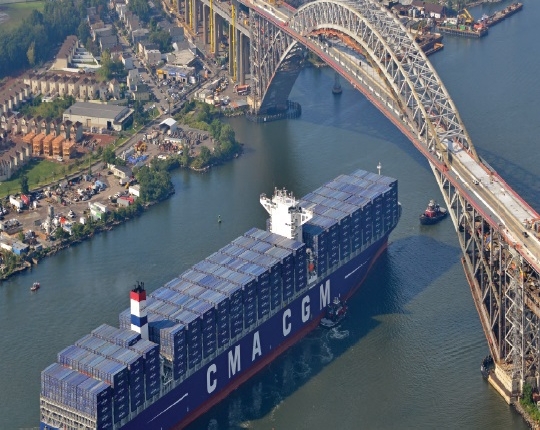
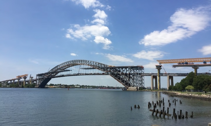
The Bayonne Bridge Navigational Clearance Project was substantially completed in February 2019, marking the first time that engineers built a new bridge deck above and through an existing roadway, while ensuring limited disruption to the traveling public. In 2006, the Panama Canal expansion project began to accommodate larger ships and absorb the growing demand of cargo. At 151 ft, the existing Bayonne Bridge was too low to allow these new “Post-Panamax” vessels access into New York and New Jersey ports. Instead of demolishing and building a new bridge, the solution was “Raising the Roadway” 64 ft. Providing access to newer, larger Panamax vessels, via the Kill Van Kull channel, the iconic arch remains a National Landmark.
Innovation of Design and/or Construction
The New York approach has 12 spans with a maximum span length of 272 ft, and a nominal bridge length of 2,379 ft. The New Jersey approach has a total of 14 spans with a maximum span length of 250 ft, and a bridge nominal length of 2,927 ft. The new main span arch deck required higher approaches on either side of the bridge. As a result, the design included a 5% rise in longitudinal slope, increasing the total length of each approach.
The Northbound bridge had to be built between the structural girders and columns supporting the existing bridge. The existing bridge constraint created the need for transverse eccentricity between the new Northbound deck and the sub-structure at the taller piers. This eccentricity created transverse over-turning moments and deflections that were mitigated by using a temporary pipe strut, shoring up the Northbound deck. Once the Southbound deck was built and the two pier caps connected, the pipe struts were removed, and the eccentricity effect was transferred as frame action between the two columns.
Consideration for the surrounding neighborhood and limited street access, led to one of the most important aspects of the design, which involved using precast segment lengths ranging from 5 ft to 10.75 ft. Coupled with a maximum segment weight of 110 tons, the varying deck widths of 65 ft for the Northbound bridge, and 51 ft for the Southbound bridge, simply meant steel super-structure was not a viable option. Precast segmental construction with overhead gantry was chosen, due to the height and length of the approaches, time constraints, and the minimal construction site space.
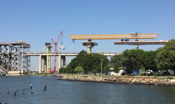
To aid in schedule, the construction team opted to crane-erect the pier-tables out ahead of the gantry with the same crawlers used for the substructure precast operation. The substructure included 513 precast units, including the capitals and caps, which weighed up to 125 tons. Column segments were epoxied together using temporary, post-tensioning bars. Once the pier cap segments were erected, loop tendons were installed and stressed, connecting the foundation to the pier cap.
Due to the deck-to-column bearing connection, temporary pier brackets were required to provide stability to the deck pier-table during construction. These pier brackets provided all necessary stability until the three-legged overhead gantry could be launched forward. Once the bridge bearings were grouted, the gantry allowed for more rapid removal of the pier brackets, mitigating the demands of the balanced-cantilever construction on the tall, slender columns. The gantry was designed to withstand all balanced-cantilever construction loads, including accidental segment drop, thus omitting potential collapse and in turn protecting the traveling public.
Superstructure consisted of 1,079 precast concrete box girders, erected using the balanced-cantilever method by overhead gantry. Another construction method utilized, was a span-by-span system installed in the gantry used at all abutment and tower end spans, which eliminated false work.
Because construction took place above live traffic – access, fall protection, and dropped object protection became an especially critical focus.
Rapid Construction
After the construction contract was awarded, an effort by the design and construction team was made to expedite the construction sequence. This was done by introducing the pipe strut as a temporary brace to counter the superstructure eccentricity on the columns. This allowed for the Northbound and Southbound structures to be precast independently.
The original design called for typical 8 and 10-finchest-long span segments. By increasing these lengths to 9 and 10.75 ft, the overall number of segments was reduced by 8%, fully expediting the casting and erection of the superstructure.
The base soffit form design included a parabolic soffit arch which required 18 segments, each with variable heights. The construction team proposed a tangent soffit that reduced the number of variable depth segments by 50%, as well as the overall post tensioning demands. This reduction allowed for a more accelerated schedule.
At the mid-point of each span, was a cast-in-place closure pour, which originally included permanent diaphragms for the future tendon profiles. The construction team was able to incorporate these tendon deviators into adjacent precast blisters, thus eliminating extensive, critical-path formwork from the closure pour cycle.
The construction team also optimized the temporary post tensioning in the substructure precast, by upsizing the bar diameter, which in turn eliminated a high percentage of permanent vertical post tensioning. The implementation of temporary erection post tensioning within the segment boxes, in lieu of the base design’s deck-anchored system, will ultimately reduce the long-term maintenance requirements for the Port Authority. Incorporating temporary blisters within these segments eliminated thousands of deck penetrations that would otherwise lead to potential long-term maintenance issues.
Aesthetics and/or Harmony with the Environment
The geometry of the precast pier cap and columns was created to replicate the architecture of the original Bayonne Bridge piers, while maintaining the efficiencies of repetitive geometry for precast construction. Taller columns were tapered to a 1:60 rate along the transverse direction for enhanced slenderness. Haunched box girders, used for the longer spans, provided an appearance of slim elegance. The final design included a mid-height pier cross-strut, that matched the bridge’s original elevation — designed as a reminder of the original 1985 National Landmark.
Cost Competitiveness
Due to height and length of bridge spans, proximity to homes, and the right of way restrictions, the most feasible erection method was a balance cantilever method using an overhead erection gantry. Also, utilizing precast construction off-line in Southern Virginia, reduced on-site labor costs and aided in accelerating the overall schedule.
Minimization of Construction Impact on the Traveling Public
Maintaining traffic during peak hours meant maximizing on full closures during off-peak hours and weekends.
Increasing the span segment length to 9 and 10.75 ft impacted more than just the schedule. As a direct result of these designs, multi-axle haulers were able to make fewer, more maneuverable trips, reducing impacts to the public.
Jury Comments
This modification preserved this 1931 US National Landmark 1,675-ft arch span by providing the additional 64 ft of vertical clearance required for port to support the “Post-Panamax” ships. The segmental bridge approach provided the tools necessary to work in the confined spaces of the surrounding neighborhoods was key to the success of this project. This project is a spectacular engineering marvel where segmental bridge techniques were leveraged to meet the demands of this new landmark bridge. This is a very exciting segmental project and is a bold example of engineering and construction ingenuity. It also serves as an example of the strengths of segmental construction as we face the challenges of rebuilding our infrastructure. Extremely difficult construction and design details developed to fit the site constraints. Aesthetically pleasing to maintain the historic nature and national landmark.
2019 ASBI Bridge Award of Excellence
Category: Bridges Over Water
State:
New York and New Jersey
Owner:
Port Authority of New York and New Jersey
Owner’s Engineer:
Port Authority Engineering Department
Designer:
HDR WSP, JV
Contractor:
Skanska, Koch, Kiewit Infrastructure Company, JV (SKK)
Construction Engineering Services:
Finley Engineering Group, Inc., Kiewit Infrastructure Engineers and McElhanney Consulting Services
Constructability Review/Estimating Services:
Kiewit Infrastructure Engineers
Construction Engineering Inspection:
Greenman Pederson Inc. (GPI)
Precast Producer:
Skanska – Bayshore Concrete Products
Formwork for Precast Segments:
Ninive
Erection Equipment:
Handan China Railway Bridge Machinery Co. Ltd (HCR)
Post-Tensioning Materials:
Schwager Davis, Inc.
Bearings:
mageba USA LLC
Expansion Joints:
mageba USA LLC
Epoxy Supplier:
Sika Corporation and Pilgrim Permocoat, Inc.
Prepackaged Grout:
The Euclid Chemical Company and Five Star


