Foothills Parkway Bridge Two – Blount County, Tennessee
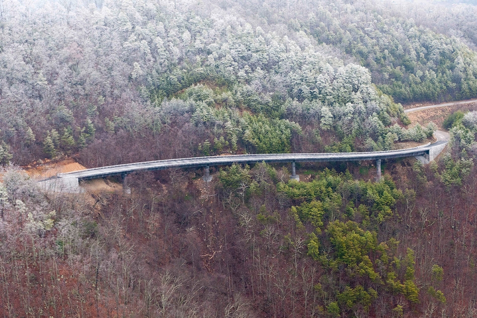
The Foothills Parkway was authorized by Congress in 1944 to provide beautiful vistas of the Great Smoky Mountains National Park from the Tennessee side of the park. The “Missing Link” of the Foothills Parkway is a particularly rugged 1.6 mile stretch of the Foothills Parkway traversing steep mountain sides that overlook Wears Valley, TN.
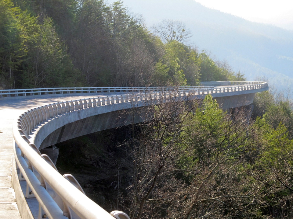
Foothills Bridge Two is located in Blount County, TN approximately 10 miles west of the North Entrance to the Great Smoky Mountain National Park. Construction of this bridge is instrumental to completing the Missing Link in that it crosses the most difficult terrain and is needed to access the construction of the Missing Link.
Innovation of Design and/or Construction
Site access only from the beginning of the bridge, and steep terrain along the entire length of the alignment required a new approach to construction that allowed various aspects of construction to be performed concurrently.
The resulting construction methodology incorporated a unique temporary work trestle that provided access along the entire bridge alignment. The work trestle was unique in that it could be reconfigured as work shifted from foundation and pier work, to superstructure segment erection.
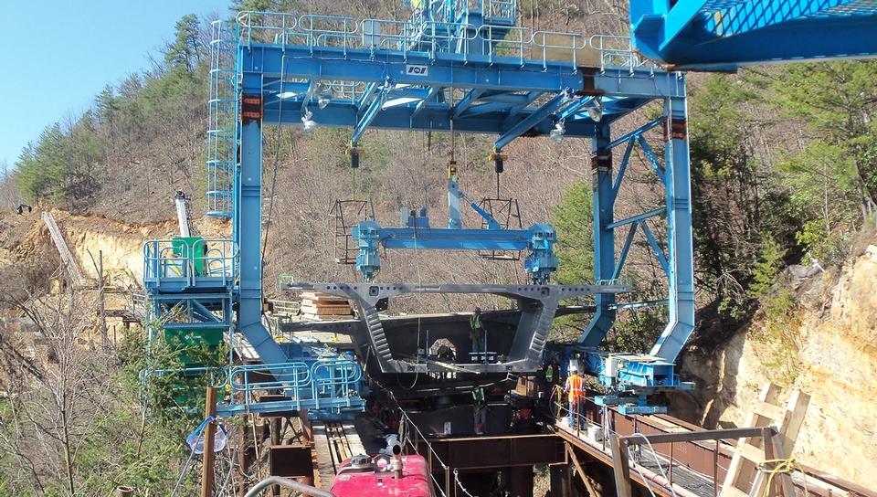
In the superstructure erection configuration a specialized segment “walker” placed segments in balanced cantilever, significantly increasing erection speed over one-direction progressive placement methods. The segment walker moves by sliding pairs of support feet, with one of the sliding feet in each pair always tied to the work trestle. This continual fixity greatly improved the safety of construction on the steep bridge grade.
The supports of the work trestle were rigid frames comprised of two steel pipe columns and a transverse steel girder. Each pipe column was supported by three, 7″ diameter micropiles and a precast triangular concrete footing. Longitudinal members of the temporary work trestle consisted of two rows of paired steel girders. The girder pairs were closely spaced and cross braced for torsional stability. The transverse spacing of the girder pairs could was adjusted depending on the configuration of the work trestle.
During trestle construction, the girder pairs were spaced closer together to support the tracks of the Manitowoc 777 crawler crane that erected the gantry. The spacing of the girder pairs was increased during superstructure segment placement to support the segment walker designed to walk past already constructed portions of the bridge.
Bridge construction began with the building of Abutment 1. From there, the trestle erection crane placed drilling equipment at the first work trestle support and micro piles were installed. The crane then placed the precast footings, support frames and longitudinal girders. Crane mats were placed over the longitudinal girders to form the deck of the work trestle. The crane then crawled forward, and this sequence was repeated until the 22 spans of the trestle were complete.
When work trestle construction had advanced beyond Pier 1, sections of the crane mat over Pier 1 were set to the side and a secondary, tire mounted 60 ton crane lowered excavation equipment to make the tiered cut for the sub-footings. When complete, the sub-footing was formed and cast. The secondary crane then lowered the equipment to drill the twenty, 9-5/8″ micro piles that support the pier. The micro piles were drilled through the sub-footing concrete. Inclined tie-backs, used to provide slope stability were also drilled through the sub-footing (Piers 1 and 2 only). Footing construction followed the installation of the micropiles and tie-backs.
The secondary crane also placed the segments of the pier. Individual segments were epoxy-joined and stressed together with four, 1-3/8″ diameter 150 ksi post-tensioning bars. All segments of the pier with the exception of the pier cap were erected at this time. Piers 2, 3, and 4 were constructed in similar fashion as construction of the work trestle was sufficiently advanced.
Pier cap placement and balanced cantilever construction began once all typical segments of Pier 1 were placed. The crane mat deck was removed and the longitudinal erection girders shifted outward to support the segment walker. The segment walker then placed the pier cap at Pier 1 and provided support for installing and stressing the four vertical 12 x 0.6″ diameter 270 ksi post-tensioning tendons.
The segment walker next placed the 4-legged cantilever construction stability tower on the footing of Pier 1. A stability tower separate from the work trestle was used for improved safety. The superstructure pier segment was then placed on the pier cap, supported by shims, and stressed down with temporary post-tensioning bars. Segments 1Up and 1Down were then placed and the cantilever stability towers engaged by supporting jacks.
Cantilever construction continued until all 20 of the 8′-8″ precast segments of the balanced cantilever were erected. The segments were epoxy-joined and stressed to the cantilever with three, 1-1/4″ diameter 150 ksi post-tensioning bars. Two of the bars were anchored in blisters cast with the segments, and could be removed and reused. The bottom bar was internal and became a part of the permanent post-tensioning system. Once each segment was assembled, the cantilever post-tensioning consisting of two 12 x 0.6″ tendons were stressed.
Superstructure continuity was made between cantilevers with a series of cast-in-place concrete closure joints and continuity post-tensioning tendons. Ten, 12 x 0.6″ strand were stressed across each closure joint. End spans were completed by placing three additional typical segments and the abutment segments, casting closure joints, and stressing continuity tendons.
The diaphragms were designed with designated future jacking points for bearing maintenance or replacement. The segments also provide room for future tendons, if needed, by providing additional post-tensioning blocks.
Rapid Construction
Though pier and superstructure construction progressed as for a typical balanced cantilever bridge, the use of the temporary work trestle and Segment Walker shortened the overall construction by one year when compared to progressive segmental construction.
Aesthetics and/or Harmony with the Environment
To protect the fragile mountainside, construction from above was utilized. Trees that were directly in the path of the bridge were topped. Root balls and top soil remained throughout the project except in the location of temporary and permanent foundations. The concrete of the piers and superstructure segments were tinted with pigment to match the natural rock outcroppings in the region. The abutments and footings were faced with granite, consistent with parkway standards. The project concluded with plantings and reforestation components.
Jury Comments
A perfect blend of functionality and context sensitive construction. The bridge is a part of and compliment to the surrounding terrain.
2013 ASBI Bridge Award of Excellence
Category: Rural Bridges and Viaducts
State:
Tennessee
Owner:
National Park Service
Owner’s Engineer:
Eastern Federal Lands,
Highway Division of FHWA
Contractor:
Bell and Associates Construction
Bridge Designer:
Corven Engineering, Inc.
Construction Engineer:
Corven Engineering, Inc.
Construction Engineering Inspection:
Corven Engineering, Inc.
Formwork for Precast Segments:
Southern Forms
Construction Estimating Services:
Armeni Consulting Services, LLC
Erection Equipment:
VSL
Post-Tensioning Materials:
VSL
Bearings and Expansion Joints:
Watson Bowman Acme – A BASF Company
Civil Engineer:
Palmer Engineering
Geotechnical Engineer:
Dan Brown & Associates
Segment Erection:
VSL
Post-Tensioning Bar Supplier:
Williams Form Engineering


