The Charles W. Cullen Bridge Over the Indian River Inlet – Rehoboth Beach, Delaware
Delaware’s new Charles W. Cullen Bridge is designed for long‐term durability, structural integrity, sustainability and aesthetics.
State Route 1 (SR‐1) runs north‐south along a narrow barrier island popular with tourists. The critical link is a bridge across a man‐made channel known as the Indian River Inlet. Since the Army Corps of Engineers first dredged the inlet in 1928, engineers have struggled to build bridges that can withstand the violent forces of sea, wind and shifting sands along the Delaware coastline. The first bridge was built in 1934, followed by new spans in 1940, 1952, 1965 and 1976, with none able to survive the harsh environs.
By the mid‐1970s, tidal scour had increased the inlet’s depth from 20 to nearly 35 feet, with the scour rate escalating about one foot each year. The extra channel depth and extreme, 100‐foot scour holes threatened to undermine the bridge’s two support piers. Seeking a permanent solution, in 2008 the owner agency awarded a $150‐million design/build contract for a new bridge. The owner stipulated a 100‐year life and no piers in the water, so the design/build team proposed a cable‐stayed bridge as the most effective, economical solution.
Learning from the lessons of the inlet’s five previous bridges, this new structure was built to last. Mother Nature has already tested the bridge, with two hurricanes, a nor’easter and an earthquake, but the bridge was designed to withstand this type of loading, and post‐event inspections have shown no signs of damage. This new bridge — exemplifying balance, harmony, ingenuity and beauty — opened for traffic in January 2012.
Innovation of Design and/or Construction
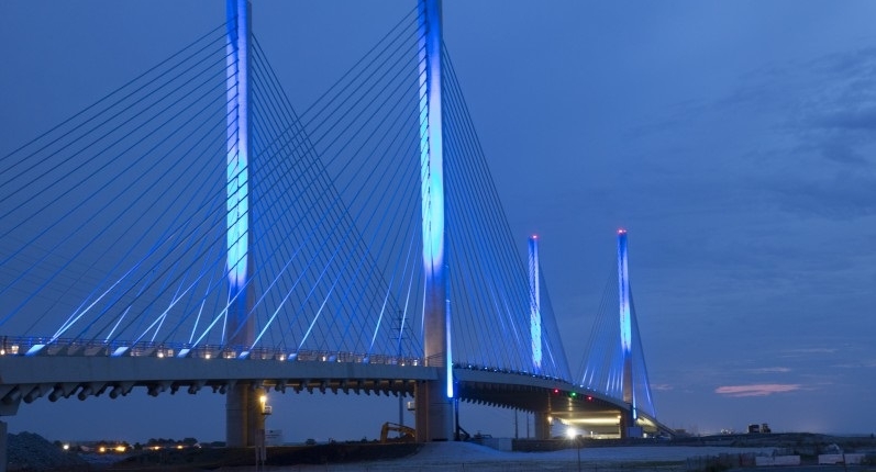
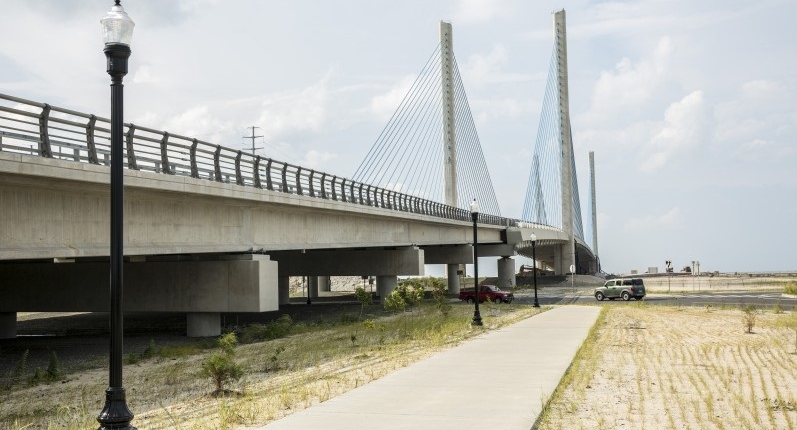
The resulting 2,600‐foot long structure compensates for the unforgiving coastal environment. With four 248‐foot tall pylons supporting a 950‐foot long main span and two flanking 400‐foot long side spans, the superstructure consists of a 106‐foot wide, six‐foot deep concrete deck supported by 152 cable stays.
Many innovative features were incorporated to increase design efficiency and constructability. The edge girders are designed to deviate around the pylons with a unique tension-and-compression concrete strut system. Each of the two continuous edge girders are six feet deep and five feet wide, with cable stays centered along the edge girders. The edge girders are configured to deviate around the pylons, allowing the girders to be aligned with the pylons and cable stays to remain in constant plane.
Another innovative solution was derived for erecting the bridge over the inlet. Since the severe scour, concerns over the existing bridge’s stability and constant, four‐knot currents prevented erection equipment from being used tension-and-compression concrete strut system. Each of the two continuous edge girders are six feet deep and five feet wide, with cable stays centered along the edge girders. The edge girders are configured to deviate around the pylons, allowing the girders to be aligned with the pylons and cable stays to remain in constant plane.
Another innovative solution was derived for erecting the bridge over the inlet. Since the severe scour, concerns over the existing bridge’s stability and constant, four‐knot currents prevented erection equipment from being used
Rapid Construction
To expedite construction and enhance cost‐efficiency, the pylons above deck level are not connected by cross struts, although conventional designs typically connect twin pylons for stability. By minimizing eccentric loading of the stays on the pylon cross section and improving the cross section’s aerodynamic characteristics by using a slender shape with rounded corners, cross struts were able to be eliminated.
Additionally, conventional cable‐stayed bridges use transverse girder spacing of 30 feet with a 12‐inch thick deck. With this bridge, a unique spacing plan places floor beams at 12 feet and cable support points at 24 feet. This tighter transverse girder spacing allowed the deck thickness to be reduced to 8-½ inches, resulting in savings in concrete weight, along with approximately 17% savings in foundations and cable‐stay quantity. To speed erection, both precast and cast‐in‐place concrete was used for the transverse girders.
Cost Competitiveness
This project’s total budget and actual cost were the same: $150 million lump sum, at an average cost per square foot of $478. The bridge was designed and constructed in just 39 months.
Aesthetics and/or Harmony with the Environment
The aesthetic objective was simple: create a graceful structure that enhances the pristine coastal landscape. The bridge’s slender lines evoke a nautical theme, with semi‐harped cable stays and soaring pylons replicating sails and masts of tall ships. At night, subtle blue lighting enhances the bridge’s visual appeal without disturbing the natural habitat. Residents and vacationers have embraced the design, expressing appreciation for its elegant shape and panoramic views.
Minimization of Construction Impact on the Traveling Public
The new bridge was constructed approximately 125‐feet west of the existing bridge, so the existing spans remained open throughout construction, providing uninterrupted travel on SR‐1. Boat traffic was also uninterrupted during construction, as the new bridge’s main span was built in cantilever over the inlet with a form traveler.
Jury Comments
The public involvement in finalizing design details has resulted in a destination and a link between barrier islands. A bridge that looks to the future as much as the immediate needs, it should be an icon for generations of tourists as well as a capable steward of public investment.
2013 ASBI Bridge Award of Excellence
State:
Delaware
Owner:
DelDOT
Designer:
AECOM
Design-Build Team:
Skanska-AECOM
Contractor:
Skanska USA Civil Southeast, Inc.
Construction Engineering Services:
AECOM (Erection Analysis) and Finley Engineering Group (Falsework)
Construction Engineering Inspection:
PB Americas, Inc.
Precast Producer:
Bayshore Concrete Products
Form Travelers for Cast-in-Place Segments:
Strukturas
Post-Tensioning Materials:
Freyssinet, Inc.
Stay Cable Materials:
Freyssinet, Inc.
Bearings:
R.J. Watson and D.S. Brown Company
Expansion Joints:
Freyssinet, Inc.
Prepackaged Grout:
Sika Corporation
Bridge Design:
International Bridge Technologies, Inc.
Structural Steel Cable Stay Anchor Boxes:
Cianbro
Wind:
RWDI
Geotechnical:
S&ME


